高通最新MSM6280资料
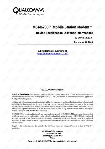
### 高通MSM6280移动站调制解调器知识点详解 #### 概述 高通MSM6280是一款先进的移动站调制解调器(Mobile Station Modem, MSM),专为满足现代移动通信需求而设计。该文档提供了关于MSM6280的关键信息和技术细节,包括其特性、接口和支持的技术标准等。 #### 范围与目标受众 本文档旨在为硬件工程师、软件开发者以及其他与MSM6280相关的技术专业人员提供必要的信息。通过这些信息,他们可以更好地理解和利用MSM6280的各项功能来开发高质量的移动设备。 #### 应用描述 MSM6280是一款高度集成的移动通信解决方案,支持多种无线通信技术,包括但不限于HSDPA(高速下行链路分组接入)、WCDMA R99(宽带码分多址)、GSM(全球移动通信系统)、GPRS(通用分组无线服务)以及EDGE(增强型数据速率GSM演进)。此外,它还支持先进的音频处理技术和多媒体功能,能够为用户提供优质的通信体验。 #### MSM6280设备特性 - **MSM6280设备一般特性**:MSM6280采用高度集成的设计,内置了强大的微处理器子系统,能够高效地处理各种复杂的计算任务。 - **HSDPA特性**:支持HSDPA技术,能够实现高达7.2 Mbps的下行链路传输速率,为用户提供更快的数据传输速度。 - **WCDMA R99特性**:兼容WCDMA R99标准,确保在不同网络环境下都能提供稳定的连接。 - **GSM特性**:支持GSM标准,能够在全球范围内提供基本的语音和数据服务。 - **GPRS特性**:支持GPRS,可实现比传统GSM网络更高的数据传输速率。 - **EDGE特性**:兼容EDGE技术,进一步提高了数据传输速率,增强了用户体验。 - **音频处理特性**:配备了先进的音频处理功能,如噪声抑制和回声消除,以提高通话质量。 - **微处理器子系统**:内置高性能微处理器,能够支持复杂的计算任务和多媒体应用。 #### 支持的接口特性 MSM6280支持多种接口特性,包括但不限于USB、SPI、I2C等,这使得它可以轻松与其他组件进行交互,提高整体系统的灵活性和扩展性。 #### 支持的多媒体特性 - **图像处理**:支持高清图像处理,能够处理高质量的照片和视频。 - **视频编解码**:支持多种视频编解码格式,如MPEG-4、H.264等,提供流畅的视频播放体验。 - **音频编解码**:支持多种音频编解码格式,如MP3、AAC等,确保高质量的音频输出。 #### 引脚描述 - **I/O参数描述**:文档中提供了详细的输入/输出引脚参数,包括电压范围、电流消耗等信息,帮助工程师更好地了解每个引脚的功能和限制条件。 - **MSM6280引脚矩阵**:提供了MSM6280所有引脚的功能说明,便于硬件设计时正确连接外部设备。 #### 电气规格 文档还详细介绍了MSM6280的电气规格,包括工作电压、最大功耗、信号电平等关键参数,这对于确保设备正常运行至关重要。 MSM6280是一款功能强大且高度集成的移动通信解决方案,支持多种无线通信技术,并具备先进的音频处理能力和多媒体功能。通过充分利用这些特性,MSM6280能够为用户提供卓越的通信体验和丰富的多媒体服务。


剩余131页未读,继续阅读

 yewing_li2012-03-01只是一份规格书,不过参考还行!!
 hoff_wu2017-01-11规格书还可以

- 粉丝: 0
- 资源: 3
 我的内容管理
展开
 我的资源
快来上传第一个资源
 我的收益 登录查看自己的收益
 我的积分
登录查看自己的积分
 我的C币
登录后查看C币余额
 我的收藏
我的收藏  我的下载
我的下载  下载帮助
下载帮助

 前往需求广场,查看用户热搜
最新资源
- 昆仑通态MCGS与3台欧姆龙E5*C温控器通讯程序功能:通过昆仑通态触摸屏,实现对3台欧姆龙E5CC温控器 设定温度值,读取实际温度,设定报警值,设定报警类型,报警上下限功能 反应灵敏,通讯稳定可靠
- 大电流电动工具,电动螺丝刀,电锯批量方案,12V,30A FOC控制
- 三菱FX3G两轴标准程序,XZ两轴,包含轴点动,回零,相对与绝对定位,只要弄明白这个程序,就可以非常了解整个项目的程序如何去编写,从哪里开始下手,
- 昆仑通态MCGS与2台台达VFD-M变频器通讯程序实现昆仑通态触摸屏与2台台达VFD-M变频器通讯,程序稳定可靠 器件:昆仑通态TPC7062KD触摸屏,2台台达VFD-M变频器,附送接线说明和设置说
- MATLAB代码:考虑安全约束及热备用的电力系统机组组合研究 关键词:机组组合 直流潮流 优化调度 参考文档:店主自编文档,模型数据清晰明了 仿真平台:MATLAB+CPLEX gurobi平台
- c#上位案例,动态添加控件 1、这是个上位机案例,自己写来通过电脑监控kuka机器人信号的工具; 3、软件界面上可以动态添加要监控的信号,可以强制输出信号 4、有c#源代码,可以作为上位机与机器人通
- 三菱FX3U与力士乐VFC-x610变频器通讯程序三菱FX3U与力士乐VFC-x610变频器通讯案例程序,有注释 并附送程序,有接线方式,设置 器件:三菱FX3U的PLC,力士乐VFCx610变频
- 台达DVP PLC与3台力士乐VFC-x610变频器通讯程序 程序带注释,并附送昆仑通态程序,有接线方式,设置 器件:台达DVP ES系列的PLC,3台力士乐VFC-x610系列变频器,昆仑通态 功
- FPGA开发:实现数码管+1602双通道秒表(联系后留邮)按键切秒表模式,所用开发板DE2-115,代码可移植,内含FPGA驱动1602代码,代码有详细注释
- 汇川PLC AM403-CPU1608TN,2020产品基于CODESYS平台二次订制软件,支持16轴ethercat总线,自带以太网 USB CANOPEN 2路485,16高速输入8高速输出,功能
- 电力电子、电机驱动、数字滤波器matlab simulink仿真模型实现及相关算法的C代码实现 配置C2000 DSP ADC DAC PWM定时器 中断等模块,提供simulink与DSP的联合仿
- labview.通用OCR识别技术
- FoobarCon_v0.9.91.0.apk
- 华为HarmonyOS应用开发者高级认证,官方专业证书
- 华为HarmonyOS应用开发者高级认证,官方专业证书
- 51单片机四层电梯控制器 基于51单片机的四层电梯控制系统 包括源代码和proteus仿真 系统硬件由51单片机最小系统、蜂鸣器电路、指示灯电路、内部按键电路、外部按键电路、步进电机、ULN2003


 信息提交成功