


CoPEC
1
ECEN5807
ECEN5807 supplementary notes
Introduction to MATLAB/Simulink
for switched-mode power converters
ECEN5807
Colorado Power Electronics Center
University of Colorado, Boulder

CoPEC
2
ECEN5807
1.1 Getting started with MATLAB/Simulink
• Starting and running simulations in MATLAB/Simulink
• Constructing Simulink models
•Examples:
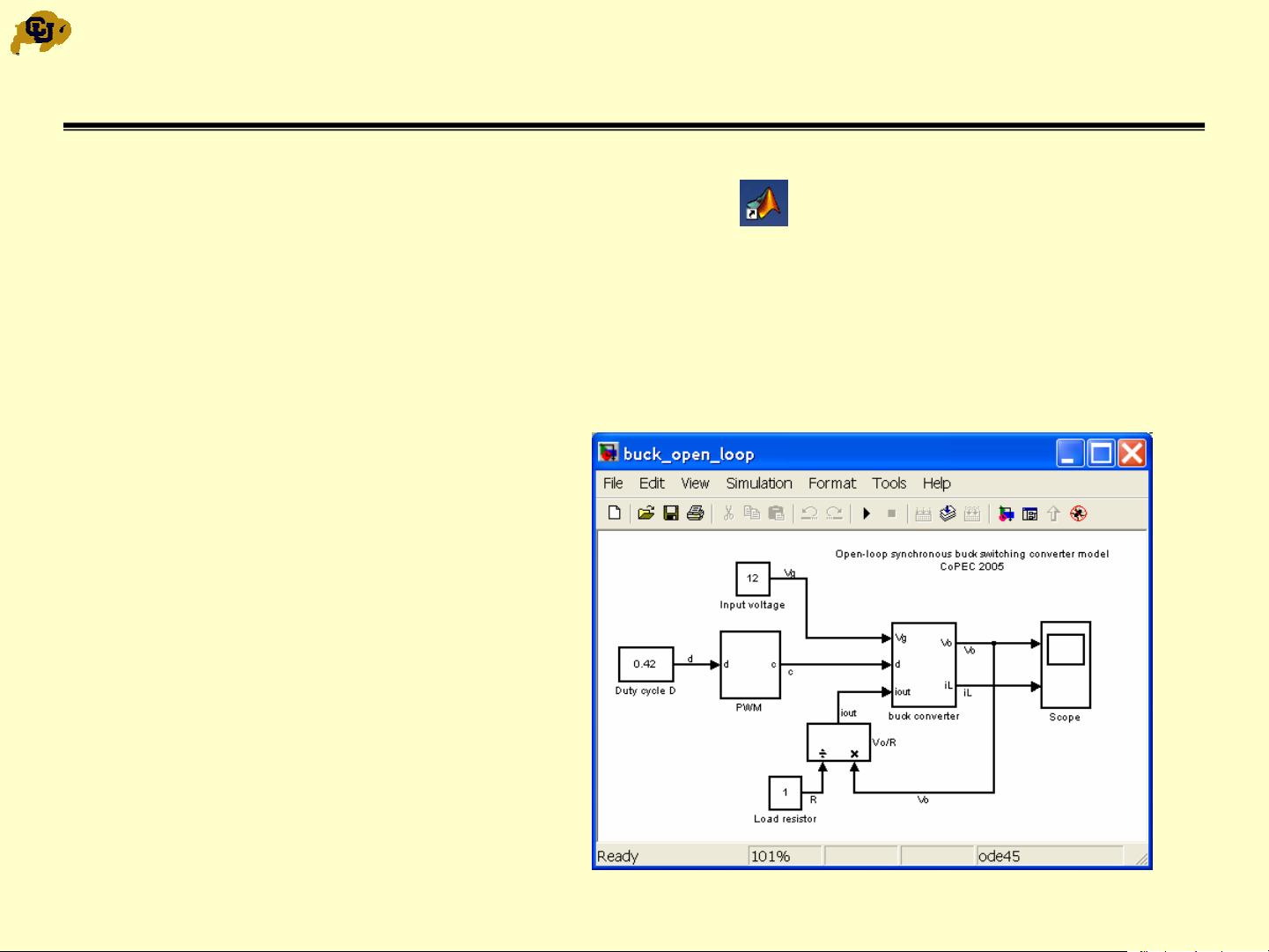
• Open-loop synchronous buck converter model
Simulink file: buck_open_loop.mdl
• Buck converter and PWM subsystem models
• Closed-loop synchronous buck converter model with an analog controller
Simulink file: buck_closed_loop.mdl
• Load transient model and simulations
Simulink file: buck_closed_loop_load.mdl
1.2 Digitally controlled buck converter: Simulink models and simulations
• System model
• A/D converter, discrete-time compensator, and DPWM models
Simulink file: buck_closed_loop_discrete.mdl
ECEN5807 supplementary notes
CoPEC
3
ECEN5807
1.1 Starting MATLAB/Simulink
•Start MATLAB:
(double-click on the MATLAB shortcut)
• Open a file, in the MATLAB window menu:
– Select file: buck_open_loop.mdl, then Open
• This opens a pre-configured Simulink model for an open-loop synchronous
buck switching converter
• Converter parameters:
• L = 4.1 µH, R
L
= 80 mΩ
• C = 376 µF, R
esr
= 5 mΩ
• f
s
= 100 KHz
• V
g
= 12 V, D = 0.42
• Load R = 1 Ω

CoPEC
4
ECEN5807
Transient Simulations in Simulink
• Make your copy of the Simulink model for further edits
In the current Simulink window:
– File Æ Save As Æ File Name: enter my_buck_open_loop.mdl,thenSave
• Check or adjust simulation parameters:
– Simulation Æ Simulation parameters
• This opens a window to adjust simulation parameters such as Start Time, Stop
Time, solver options, step size, etc.
• The default parameters and
options are usually fine, except:
– Enter appropriate Stop time
(3 ms in this example)
–Enter Max step size of
about 1/100 of the switching
period (0.1 µs in this
example)

CoPEC
5
ECEN5807
Starting Transient Simulation
• In the current Simulink window:
– Simulation Æ Start or
click on the Start button in the toolbar
Current simulation time and
progress are shown here


评论0