Work with the Motion Path behavior
The following tasks demonstrate how to customize the Motion Path behavior.
With an applied Motion Path behavior selected in the Layers list, Timeline, or Behaviors Inspector, do any of the following:
In the Behaviors Inspector in Motion, click the Path Shape pop-up menu, then choose a shape option.
If Path Shape is set to Open Spline or Closed Spline, double-click the motion path in the canvas to add control point points, and then edit the points. See Intro to editing control points.
If Path Shape is set to Circle, Rectangle, or Wave, drag the transform handles in the canvas.
If Path Shape is set to Geometry, modify the shape of the source geometry.
You can use a shape animated with behaviors or keyframes as the source for a motion path. This includes animated transforms (a shape changing its location in the canvas) and animated control points (a shape changing its shape due to keyframed control points).
In Motion, import (or draw) the shape to use as the path source.
With an applied Motion Path behavior selected, open the Behaviors Inspector, then choose Geometry from the Path Shape pop-up menu.
The Shape Source well appears in the Inspector and HUD.
From the Layers list, drag the shape you created in step 1 into the Shape Source well, and when the pointer becomes a curved arrow, release the mouse button.
A thumbnail of the shape appears in the well and the shape is used as the source shape for the motion path.
Note: You can disable the source shape in the Layers list (by deselecting its activation checkbox) so that the source shape is not visible in your project.
In Motion, with an applied Motion Path behavior selected, open the Behaviors Inspector, click the To pop-up menu (located next to the Shape Source well), then choose the object to use as the motion path’s shape source.
Note: To align the rotation of the object to the shape of its motion path, you can apply the Snap Alignment to Motion behavior (in the Basic Motion behaviors subcategory).
In the Layers list or canvas in Motion, select the object (not the Motion Path behavior), then drag the object in the canvas.
Note: To move the object and its motion path when Path Shape is set to Geometry, select the source object, then move the object in the canvas.
By default, the object is locked to the motion path by its anchor point.

In the canvas toolbar in Motion, click and hold the transform tools pop-up menu, choose Anchor Point, then drag the anchor point in the canvas.
For more information on using the Anchor Point tool, see Move a layer’s anchor point.
Note: A separate Offset parameter lets you offset the starting location of the object on the motion path (but does not offset the object from the path).
In the Layers list in Motion, select an applied Motion Path behavior.
In the Behaviors Inspector or HUD, click the Speed pop-up menu, then choose Custom.
The Custom Speed parameter control becomes available. By default, a keyframe is set at the first and last points of the behavior to create an animation of 0 percent to 100 percent, where at 0 the object is at the beginning of the path, and at 100 the object is at the end of the path. This is the same velocity used with the Constant preset.
Press A to turn on keyframe recording.
Note: When keyframe recording is on, all keyframeable parameter value sliders are tinted red, to remind you that any value change entered creates a keyframe.
Move the playhead to the position where you want to create a keyframe, then enter a percentage value in the Custom Speed field.
For example, a value of 90 moves the object 90 percent of the way through the motion path.
Continue moving the playhead and adding keyframes to obtain the result you want, then press A again to turn off keyframe recording.
Note: If you change the Speed parameter to a preset (such as Constant) after creating a custom speed, the custom velocity channel is ignored but remains intact.
The easiest way to modify a motion path in 3D space is to add a camera to your project and manipulate the path in a modified camera view.
If there’s no camera in your Motion project, add a camera by doing one of the following:
In the toolbar, click Add Object, then choose Camera from the pop-up menu.
Choose Object > New Camera (or press Option-Command-C).
Note: If none of your project groups are set to 3D, a dialog appears asking if you want to switch your 2D groups to 3D groups. Click Switch to 3D to allow the camera to affect the groups.
Do one of the following:
Click the pop-up menu in the upper-left corner of the canvas (the default option is Active Camera), then choose a camera view. This example uses the Top view.
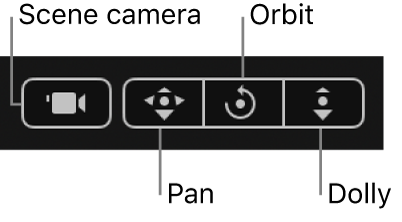
With the Active Camera (or another camera view) selected, drag in the Orbit tool (the center tool in 3D view tools in the upper-right corner of the canvas) to rotate the camera manually to a new view.

Note: If you use the 3D view tools with any camera selected, you are moving the camera, not just changing the camera view.
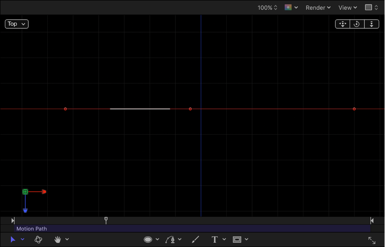
Depending on the camera view, the object on the path might not be visible. For example, if the object has not been rotated in X or Y space and you are working in Top view, the camera is looking down perpendicularly (on the Y axis) on the object. The motion path and its points are still visible (as long as the Motion Path behavior is selected).
In the following image, the motion path appears flat when viewed from above—the affected object only moves in X and Y space.

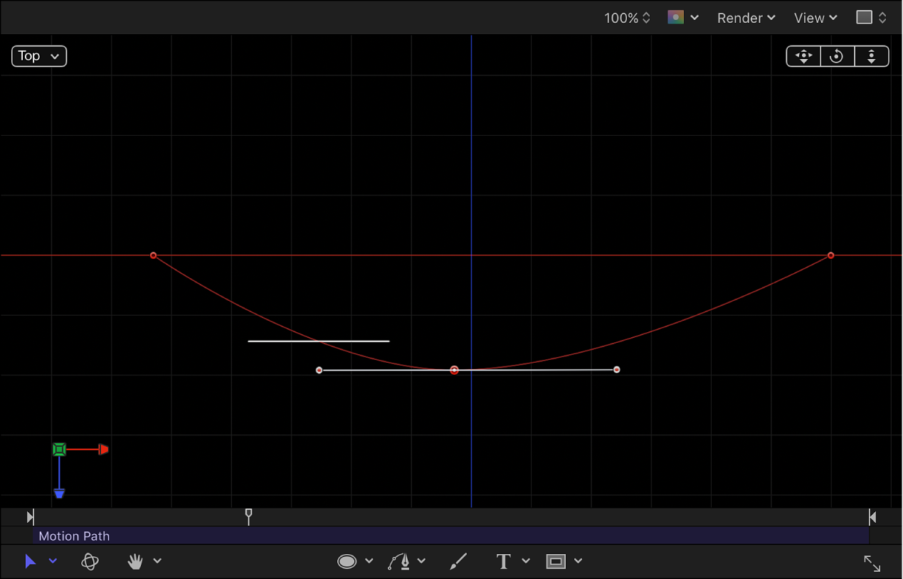
Drag a control point up or down to adjust the object in Z space.
In the following image, the path is no longer flat—the affected object moves in X, Y, and Z space.

To enter specific values for the control point locations, click the Control Points disclosure triangle in the Motion Path behavior parameters. The first value field is X, the second value field is Y, and the third value field is Z.
To reset the camera view, do one of the following:
Double-click the 3D view tool that you previously adjusted. For example, if you dragged the Orbit tool to rotate the current camera, double-click the Orbit tool to reset the camera.
If you chose (or modified) a default camera view (such as Top, Right, Left, and so on), choose Active Camera from the Camera menu, or choose View > 3D View > Active Camera.
With the camera selected, click the reset button in the Properties Inspector.
For more information about working with cameras in a 3D project, see Intro to 3D cameras.
Download this guide: PDF